IEC-60909 Short-Circuit in EasyPower
Introduction
EasyPower offers a complete and accurate solution to short-circuit calculations in three-phase AC systems using the IEC-60909 standard. You can enter equipment data and parameters via user friendly interface. The results meet requirements of IEC-60909 and match the example provided in IEC TR 60909-4 section 6. The IEC standard terminology is used in the user interface and reports.
EasyPower supports the following four types of short-circuit conditions as per IEC 60909:
- 3-phase short circuit
- Line-to-line short circuit
- Line-to-line short circuit with earth connection (double line-to-earth)
- Line-to-earth short circuit.
Calculated Values
You can obtain the following values of short-circuit currents at the fault location for both maximum and minimum short circuit currents:
- Initial symmetrical short-circuit current (Ik”)
- Peak short-circuit current (ip)
- Symmetrical short-circuit breaking current (Ib) at 0.02s, 0.05s, 0.1s and 0.25s
- DC component (idc) of short circuit-current at breaking times
- Steady-state short-circuit current (Ik)
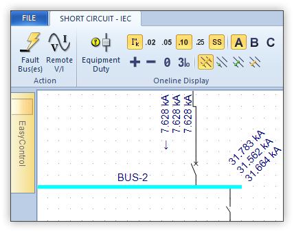
Figure 1: Display of short-circuit currents
You can view the currents in various formats such as phase currents for A, B and C phases or in symmetrical components: positive sequence, negative sequence, zero sequence and the 3I0 value (3 times the zero sequence current). Corresponding voltages can be displayed at the buses. The values can be displayed in magnitude, magnitude and angle, or in real and imaginary quantities.
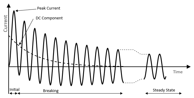
Figure 2: Short-circuit currents decaying over time
Methodology
EasyPower uses the equivalent voltage source at the short-circuit location, symmetrical components impedance network, and the voltage factor c as described in section 2.3 of the standard. The short-circuit impedances for electrical equipment are modified using impedance corrections factors that are calculated based on section 3. Impedance correction factors are applied for network or utility (KQ), generators (KG), power stations units with on-load tap changer (KS), power stations units without on-load tap changer (KSO), and two- and three-winding transformers (KT). The resistances for cables, transmission lines and busways for maximum short-circuit current calculations are based on the conductor temperature at 20°C. For minimum short-circuit currents, the resistances are based on the estimated temperature at the end of the short-circuit condition. The resistance to reactance (R/X) ratios for different equipment can be calculated as per recommendations in the standard or entered by users as per the manufacturer data. For minimum short-circuit calculations the motor contribution is excluded. Capacitors and non-rotating loads are not included in the calculations. The program is designed to address short-circuits in meshed networks.
Voltage Factors (c)
The voltage factor c is used to scale the equivalent voltage source in the calculations to account for variations in the system voltage. This factor is also used in calculating impedance correction factors. EasyPower uses the following c factors as the default for maximum and minimum short-circuit conditions. You can modify these values as needed in the short circuit options.
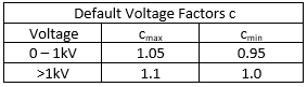
Table 1: Default Voltage C Factors
Impedance Corrections Factors
EasyPower applies impedance correction factors in short circuit calculation based on IEC-60909-0 standard.
Transformer Impedance Correction Factors
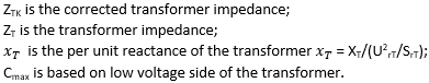
The transformer correction factor KT for two winding units with or without on-load tap changer (LTC) is calculated as follows per section 3.3.3 equation (12a).
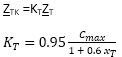
Where
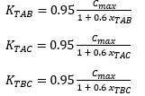
The correction factors for three-winding transformers with or without LTC are calculated using the following equations.
Synchronous Generator Impedance Correction Factor
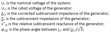
The synchronous generator impedance correction factor KG for generators without unit transformers is calculated as follows per section 3.6.1 equations (17) and (18).
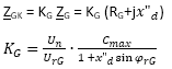
Where
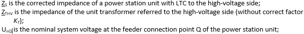
Impedance Correction Factor for Power Station Units with On-Load Tap Changers
The corrected impedance ZS and impedance correction factor KS for whole power station units with OLTC are calculated as follows per section 3.7.1 equations (21) and (22).
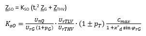
Where
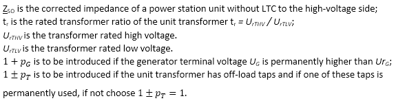
Impedance Correction Factor for Power Station Units without On-Load Tap Changers
The corrected impedance ZSO and impedance correction factor KSO for whole power station unit without OLTC are calculated as follows per section 3.7.2 equations (23) and (24).
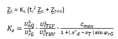
Where
Initial Symmetrical Short-Circuit Current (Ik”)
The initial symmetrical current is calculated based on section 4.2. This is the first step to obtaining most values. Subtransient impedances are used for rotating machines with the impedance correction factors. As described in the methodology the solution is obtained using the equivalent voltage source at the short-circuit location, symmetrical components impedance network, and the voltage factor c.
Peak Currents (Ip)
EasyPower calculates the Peak currents (ip) based on section 4.3 of IEC-60909-0 standard. The following methods are supported for meshed networks as per section 4.3.1.2:
- Peak current based on method (b): This method applies the 1.15 multiplying factor as a conservative approach as provided in equation (58) of the standard.
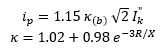
The 1.15 factor is used only when the impedance R/X ratio of any branch contribution to the short circuit location is equal to or greater than 0.3.The product 1.15κ(b) is limited to 1.8 for low voltage and 2.0 for high voltage.
The method described above is for 3-phase short circuit. For unbalanced short circuit (line to line, line to earth, and double line to earth), the factor κ is calculated from the R/X ratio of three phase short circuit at the same location. The implementation is as per sections 4.3.2 through 4.3.4 in the standard.
- Peak current based on method (c): This method uses calculation of equivalent frequency (fc) based R/X ratio. As per section 4.3.1.2(c), a separate network computation is performed for all inductive reactances scaled down to 40% of the system frequency (24 Hz for 60 Hz systems and 20 Hz for 50 cycle systems). Also, all synchronous machines use the resistance RGf in place of RG in accordance with section 3.6. The default values for RGf are calculated based on voltage, MVA rating of the machine. From the equivalent network, the R/X is obtained by multiplying the fc frequency Thevenin impedance Rc/Xc ratio by 0.4, as given in equation (59a) of the standard. This R/X is then used to calculate the factor κ.
The method described above is for 3-phase short circuit. For unbalanced short circuit (line to line, line to earth, and double line to earth), EasyPower provides the option of using the factor κ based on the unbalanced short-circuit Thevenin impedance equivalent R/X ratio or based on the 3-phase short-circuit at the same location. The implementation is as per sections 4.3.2 through 4.3.4 in the standard.
Symmetrical Short-Circuit Breaking Currents (Ib)
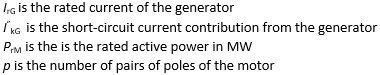
For rotating machines the current contributions to short-circuit decays over time. Breaking currents are calculated at 0.02s, 0.05s, 0.1s and 0.25s based on section 4.5 using the meshed network approach. Current decrement factor µ is applied to increase the reactances of generators and motors, and an additional current decay factor q is used for asynchronous motors using equations (70) and (73) respectively. µ is set to 1 when the ratio I"kG/IrG is less than 2.
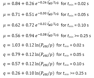
Where,
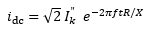
DC component (idc)
DC component of short-circuit current at breaking times: Following section 4.4 and equation (64), the dc currents are calculated from initial symmetrical short-circuit current and equivalent frequency based R/X ratio table for meshed network.
Steady-state short-circuit current (Ik)
Steady-state short-circuit current (Ik) is calculated based on section 4.6 for meshed networks using equations (84) and (85). Motor contributions are excluded. For unbalanced faults, equations (86), (87), (88) and (89) are used.
Asymmetrical Currents
Asymmetrical currents for the initial and the four breaking time intervals are also calculated for use in protective device coordination. Asymmetrical currents are calculated as the root mean square of the symmetrical and dc components.
Asymmetrical values can be used with protective devices that respond to the asymmetrical currents.
Remote Currents and Voltages
Currents flowing through sources, cables, lines, transformers and other equipment are also calculated. Voltages at remote buses are also provided. These remote currents and voltages are useful for relay setting.
EasyPower Results compared with Example in IEC 60909-4
IEC 60909-4 section 6 provides a sample calculation as a benchmark test for software programs to compare. The comparison of results is summarized below.
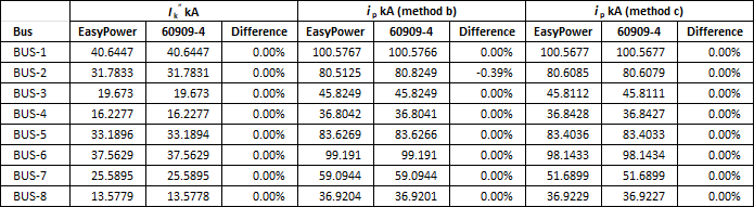
Table 2: Three-phase short-circuit currents for Initial symmetrical rms (Ik” ) and peak (Ip)
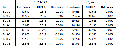
Table 3: Three-phase short-circuit currents for breaking (Ib at0.1s) and steady state (Ik)
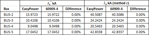
Table 4: Line-to-earth short-circuit currents for Initial symmetrical rms and peak
Short-Circuit Duty Calculations
EasyPower compares the short circuit results with protective device short-circuit ratings and displays the results in the text report and in the single line diagram. For high voltage circuit breakers, the peak current is compared with the making capacity and the breaking current is compared with the rated breaking capacity. Fuses and low voltage circuit breakers ratings are compared with initial currents. Switches use the peak current to compare with making capacity. Based on the test X/R ratio specified in the respective IEC standards for equipment, the calculated short circuit duty currents are adjusted when the short circuit X/R is greater than test X/R. High voltage circuit breaker data comes with the DC time constant. This data is used to calculate the test X/R ratio for the circuit breaker. The EasyPower library is populated with data for circuit breakers, fuses and switches. The short circuit rating is part of the data library.
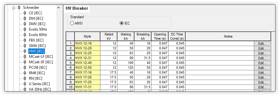
Figure 3: Example HV breaker ratings in the device library
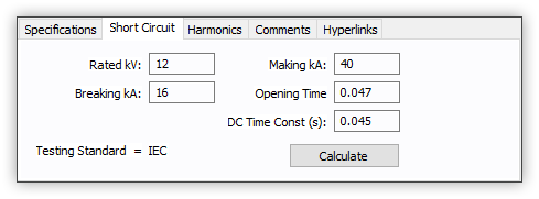
Figure 4: Ratings for HV breaker in project file loaded from the library
In the equipment short-circuit duty report, comments and text colors provide indication of problem areas. When the short-circuit current exceeds the ratings for the device the results are shown in red and the comment output is VIOLATION. EasyPower provides the option of showing a warning when the short-circuit duty percent is above a user defined safety margin threshold but below the violation level. The default threshold is -10% of the rating for warning.
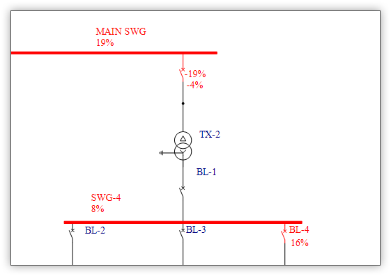
Figure 5: Short-circuit duty results displayed in the single line drawing
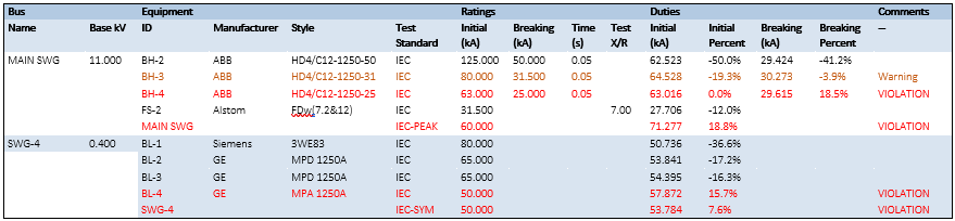
Table 5: Short-circuit equipment duty report
Voltage Sensitivity Analysis
Short-circuit on any bus results in voltage drop in other near buses in the system. You can set a voltage sensitivity threshold in the options such that any bus with voltage below this value will be highlighted red in the single line view and shown in the voltage sensitivity report.
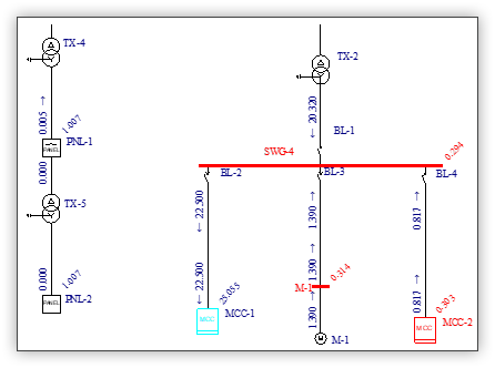
Figure 6: Highlighting of buses when voltage is below threshold
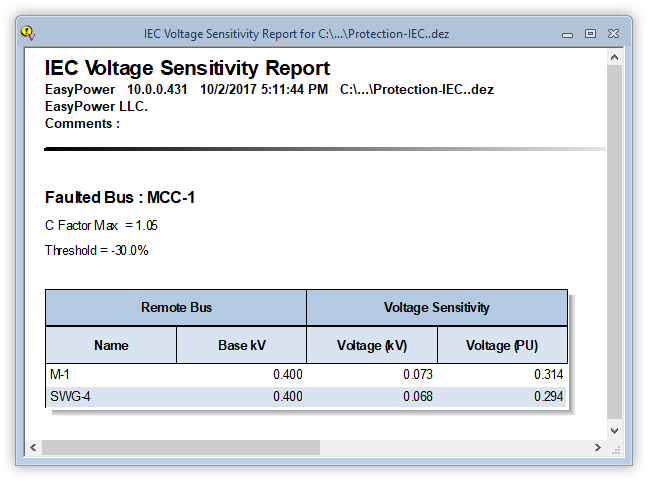
Figure 7: Voltage sensitivity report for buses with voltage below threshold
Transformer Phase Shift
The short-circuit calculation provides the phase angle of the branch currents and the bus voltages at various equipment. The phase angles displayed are relative to the applied equivalent voltage source being at zero angle. Transformers having different winding configurations, such as a delta connection on one side and a star (wye) connection on the other side, have a designated shift in the phase angles of currents and voltages. For remote buses and branches across transformers, a phase angle shift is applied accordingly by the short circuit calculations.
IEC 60076-1 standard specifies clock number notation and their respective phase angle shift for transformers. EasyPower provides the necessary phase angle shift of remote voltages and currents for IEC rated transformers in the IEC short circuit analysis. For transformers with delta and start (wye) winding connections, the clock notations 1,3,5,7,9 and 11 are supported in the database. These have 330, 270, 210, 150, 90, and 30 degrees phase shift respectively based on the high voltage side taken as the reference. For ANSI rated transformers, a fixed +30/-30 degrees phase shift is applied.
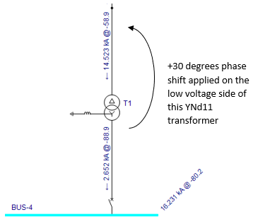
Figure 8: Shift in current angle across delta-wye transformer
Integration with Protective Device Coordination
The IEC 60909 short-circuit results are integrated with the protective device coordination tools in EasyPower. The following features are supported:
- View of the single line diagram in the time current characteristics (TCC) plot for protective devices.
- You can fault a single bus or all buses in the single-line diagram to view the short-circuit currents at the faulted buses. You can also view the remote branch currents and remote bus voltages.
- The short-circuit current through any protective device can be used to clip the TCC curve of the device. This will display the curve only up to the maximum current the device will see. For TCC clipping you can choose one from initial, breaking and steady state currents.
- You can insert tick marks (arrows) in the TCC plot to indicate the short-circuit current through the device. You can display short-circuit tick marks for initial, breaking and steady state currents. For breaking current you can choose from 0.02s, 0.05s, 0.1s or 0.25s.
- For phase TCC clipping and tick marks, EasyPower automatically selects the asymmetrical currents for low voltage circuit breakers, fuses and electromechanical relays. Symmetrical currents are applied for relays with DC offset filter. For phase currents, the maximum current of the three phases is used.
- Earth (ground) trip functions for low voltage circuit breakers or relays use the symmetrical earth (ground) current. This is the 3I0 value (3 times the zero sequence current).
- Zone Selective Interlocking (ZSI) is simulated using IEC short-circuit currents. In a system of low voltage breakers with ZSI, when the current through any circuit breaker exceeds the short time pickup its restraining signal is sent to upstream circuit breakers. The upstream circuit breakers do not trip instantaneously whereas the most downstream circuit breaker trips fast, enabling selective coordination.
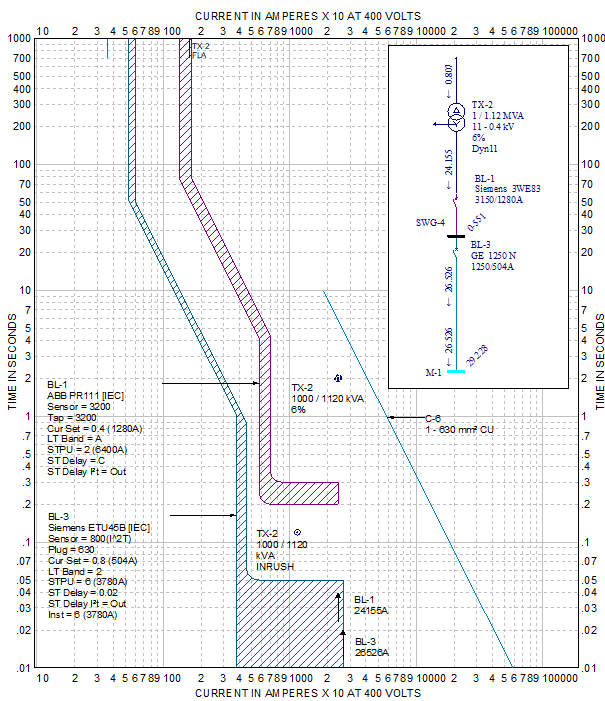
Figure 9: Time-current characteristic curves showing device curves clipped at the right side and short-circuit tick marks