Transferred Voltage Hazards
Hazardous touch voltages may be transferred to structures that seem inconspicuous and locations that have no warning signs of a possible shock hazards. Before diving into this transferred voltage discussion, please make sure you are familiar with concepts of a typical grounding system and their design as discussed in the Grounding Analysis article. The concepts of a grounding system analysis are applied to evaluate and resolve the unique interactions that are described as transferred voltage hazards.
Free Intro to Grounding Analysis Book
 Learn more about the concepts in this article and related content in the Introduction to Grounding Analysis Book download for free! This free book serves those in the power industry responsible for analyzing the performance of a grounding (earthing) system, specifically with regard to IEEE Std 80, Guide for Safety in AC Substation Grounding. It is a comprehensive and valuable resource that shows the need for and how to do grounding analysis.

For a typical grounding system analysis, the focus is assuring the voltage is sufficiently reduced between equipment and the soil such that touch and step voltages are below permissible limits within the site. A transferred voltage is defined as a touch voltage scenario where a voltage is transferred into or out of a station to or from an external point. The illustration below provides a visual representation of typical touch and step voltage hazards as compared to a transferred voltage hazard. There are three individuals located within a substation that, when properly designed, should be protected from hazardous magnitudes of touch and step voltages. The substation’s fence is directly connected to an adjacent chain link fence that presents a transferred touch voltage hazard for the fourth individual outside the site.
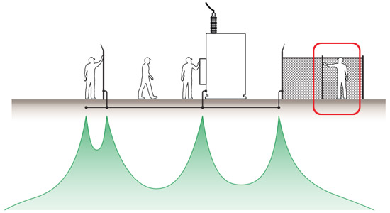
The ground potential rise is not limited to the site’s property line and transferred voltages may propagate through the soil medium or direct metallic conduction. The example above illustrates direct metallic conduction. Metallic objects, such as a buried tank in contact with the soil, may be a recipient for transferred voltages via soil conduction. The recipients of transferred voltages may influence the earth’s surface potential adding to the analytical complexity of these studies. The image below shows the indent in the ground potential rise above the buried metallic tank.
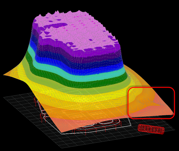
The buried metallic tank is only 50 feet (15 m) and thus the metallic tank has an equal voltage throughout, and this uniform voltage distorts the soil surface potential. Even with the effects of the tank, the soil’s potential varies by hundreds of volts in that 50-foot span. In the safety plot below, green indicates areas that touch voltages are within permissible limits while yellow indicates locations where the touch voltage exceeds permissible limits.
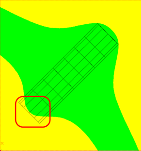
Most areas above the buried tank show voltages are within permissible limits, but any individual in contact with an above grade valve in the yellow regions may be susceptible to fatal shock hazards. This is just one scenario of voltage transferring through the soil to a metallic tank but there are other recipients to consider.
Recipients of Transferred Voltages
Metallic objects can become a recipient of transferred voltage, but common recipients include:
- Pipelines
- Fencing
- Buildings
The first challenge is recognizing possible transferred voltage hazards at recipients. Pipelines are below grade and often the first challenge is simply knowing their location. This can be especially challenging when the pipeline and power system are operated by different entities. Even buildings and fencing can be a challenge to determine if a transferred voltage hazard may occur. The magnitude and extent of a grounding system’s ground potential rise is one significant factor in determining transferred voltage hazards. The mode of transfer and geometry of the recipient in relation to the power system can also determine the significance of transferred voltages.
Bonding or Isolating to Resolve Transferred Voltages
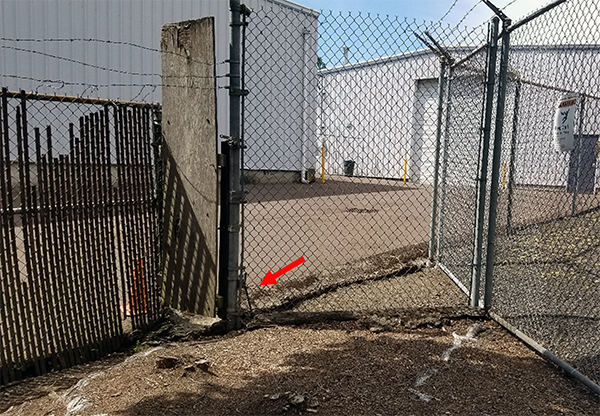
In systems with direct metallic transferred voltages, providing some insulation and isolation can frequently resolve possible hazards. From a bonding and grounding approach, safety is maintained by keeping equipment and soil voltages as close to an equipotential as possible. Removing ground leads may appear to create a safety hazard, when it is truly a mitigation effort to resolve transfer voltages. This confusion from typical practice to analyzed solution can cause mitigation approaches to be removed during routine maintenance of power systems. The photo below indicates an air gap from the power system fence to the orthogonal fence, but a ground lead to the bottom left corner allows direct conduction to the neighboring facility’s fence.
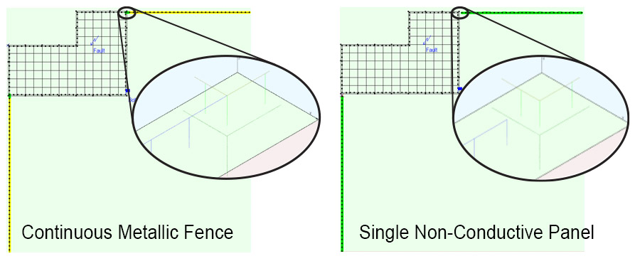
The XGSLab case study illustrates the voltage potential, showing that touch voltages exceed permissible limits when in direct connection to the substation, as shown by the yellow areas in the safety plot (left). Removing the direct metallic connection, the voltage between the fence and the soil are below permissible limits in the green areas:
In another example, transferred voltages conducted through the soil may be confusing at first as the fence is exceeding permissible limits at the power system and away from the power, but acceptable touch voltage between.
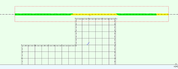
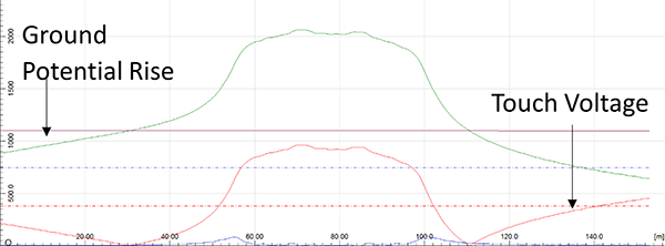
Comparing the earth’s surface potential near the grounding system, the soil’s potential is elevated above the fence potential resulting in unacceptable touch voltages. As the ground potential drops off farther from the grounding system, the fence potential is now elevated above the soil potential again resulting in unacceptable touch voltages. With an accurate analysis software, such as GSA_FD, engineers can evaluate the effectiveness of multiple mitigation strategies to promote efficient design providing personnel and public safety. Testing is highly recommended to validate data entry contributes to an accurate result for real world design.
For more information on this subject, please view the Evaluating Transferred Voltage Webinar video.
XGSLab™ Grounding Solution
XGSLab is one of the most powerful software for electromagnetic simulation for power, grounding and lightning protection systems and the only software on the market that takes into account International (IEC/TS 60479-1:2005), European (EN 50522:2010) and American (IEEE Std 80-2000 and IEEE Std 80-2013) Standards in grounding system analysis.